 +86-21-63353309

planetary gear simulator
3D Printable Planetary Gear : 7 Steps (with Pictures) - Instructables

First off, assembling the sun gear is simple; take the threaded axle and screw it into the hole opposite of the other axle of the sun gear. Next, prepare the planetary gears by inserting each onto the three axles of the male bracket. It doesn't matter which one goes where on it, as each of these are the same. Add Tip.
Planetary gear ratio calculations
The pitch diameter of a gear is just the number of teeth divided by diametrical pitch (larger values of "diametrical pitch" mean smaller teeth). The gear generator program tends to refer to tooth spacing. Pitch diameter can also be calculated as tooth spacing * number of teeth / (2*π), where 2*π = 6.283. Here's another planetary gear set.
Transmission Design and Kinematics Simulation of Fixed

Abstract: Based on the theory of 2K-H planetary gear ransmission, a fixed-axis gear planetary gear transmission scheme is designed, the gear meshing
Power Flow Simulation for Two-Degree-of-Freedom Planetary Gear

Power Flow Simulation for Two-Degree-of-Freedom Planetary Gear Transmissions with Experimental Validation: The basic relationships among gear ratios, velocity succession, torque directions, power ratios, energy losses, and efficiency are derived from first principles. The techniques presented here can be applied to ordinary, planetary, or mixed gear trains.
How to Set Up a Planetary Gear Motion with SOLIDWORKS
Add a configuration called "Ring Gear Fixed.". Right-click the Ring Gear and select Fixed, This Configuration only. To test motion, rotate the planetary gears by the Carrier for best results. For the second configuration, copy and paste the Default Configuration and rename it "Sun Gear Fixed.". Align the gears and fix the Sun Gear in
Planetary Gear Simulation files - 3D CAD Model Library | GrabCAD

Planetary Gear Simulation files - 3D CAD Model Library | GrabCAD. The CAD files and renderings posted to this website are created, uploaded and managed by third-party community members. This content and associated text is in no way sponsored by or affiliated with any company, organization, or real-world good that it may purport to portray.
Planetary Gear Set and Automatic Transmission Simulation for

The simula- tion, called ''PG-Sim'' for Planetary gear simulation, was developed in the Department of Engineering. Mechanics at the United States Air Force
Planetary Gear Simulation | 3D CAD Model Library | GrabCAD
5/2 · Planetary Gear Simulation | 3D CAD Model Library | GrabCAD. Join 9,320,000 engineers with over 4,830,000 free CAD files Join the Community. The CAD files and renderings posted to this website are created, uploaded and managed by third-party community members. This content and associated text is in no way sponsored by or affiliated with any
Gear Simulation | DriveTrain Simulation | RecurDyn/DriveTrain
Gear simulation using RecurDyn/DriveTrain. RecurDyn/DriveTrain is a solution that enables to model and simulate the components of a drivetrain consisting of gears, bearings, shaft, and other components (especially for gear simulation and bearing simulation). It consists of 3 toolkits: GearKS, BearingKS, and Shaft.
Planetary Gear Calculator - CNET Download
Design planetary gear set. User can configure module, pressure angle and number of gears. The ratio of gear is also calculated and given to
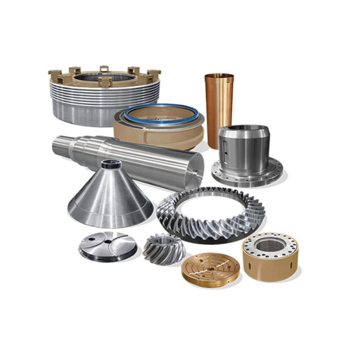
Planetary Gear Simulator Manufacture and Planetary Gear

China Planetary Gear Simulator Manufacture, Visit Here to Find the Planetary Gear Simulator That You are Searching for. Ms. vicky peng What can I do for you? +8618537916657 Contact
Leave a Comment